


 Triumph Ignition Timing - Page 2
|
Macy's Garage, Ltd. America's BEST Triumph Shop! |
Welcome to page two of our discussion of ignition timing, specifically as it applies to Triumph TR2, TR3, and TR4 sports cars. We’ve already covered the what’s and why’s of ignition timing, so now we can roll up our sleeves and get to the “how’s”.
The first how we need to know about to set the initial timing is how we know the exact moment that a spark plug is going to fire. For that answer, I need to explain how the ignition system in our Triumphs works.
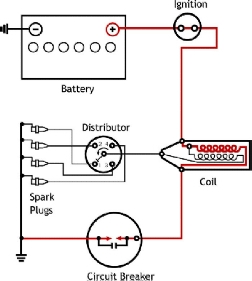 It all starts with the
12-volt battery, and electricity’s desire to flow from the positive battery
terminal to the negative battery terminal. Even though batteries were
originally installed in our Triumphs with the positive terminal connected to
ground, I’m going to explain this as if your car has been converted to negative
ground, because it seems to make more sense (at least to me). In basic terms,
electrical current flows from the positive battery terminal to the negative
terminal. The engine’s ignition system is one of many paths that the electricity
can take. The current flows from the positive battery terminal through a wire
to the ignition switch, and if the switch is “ON” continues to the “+” terminal
of the coil. Of course if the switch is “OFF”, then the current flow stops and
the ignition system is disabled.
It all starts with the
12-volt battery, and electricity’s desire to flow from the positive battery
terminal to the negative battery terminal. Even though batteries were
originally installed in our Triumphs with the positive terminal connected to
ground, I’m going to explain this as if your car has been converted to negative
ground, because it seems to make more sense (at least to me). In basic terms,
electrical current flows from the positive battery terminal to the negative
terminal. The engine’s ignition system is one of many paths that the electricity
can take. The current flows from the positive battery terminal through a wire
to the ignition switch, and if the switch is “ON” continues to the “+” terminal
of the coil. Of course if the switch is “OFF”, then the current flow stops and
the ignition system is disabled.
Now the coil is an interesting part, because it has the ability to turn the 12-volt electricity from the battery into the 20-30,000 volts (or more) needed to cause a spark to jump across the spark plug terminals. How does it do that? There are actually two coils (windings) of wire inside a “coil”, a primary coil around the outside and a separate inner or secondary coil. When electricity from the battery flows through the primary windings it produces a magnetic field, which affects the inner (secondary) windings. If the current flow (from the battery) through the primary coil windings is suddenly stopped, the magnetic field collapses, which induces a current in the secondary coil windings. The much larger number of coil windings in the secondary coil cause it to produce the high voltage necessary to jump the spark plug gap, and ignite the fuel/air mixture in your engine.
How is it that we are able to stop this flow of electricity through the primary coil windings each time that we want a spark plug to fire? That’s the job of the breaker points (usually referred to as simply “points”) in the distributor. In our example of a negative ground battery system, a small wire from the “-“ side of the coil goes to the distributor and continues inside where it connects to the points. (If your car is positive ground, then the connections to the “+” and “-“ terminals of the coil should be reversed.)
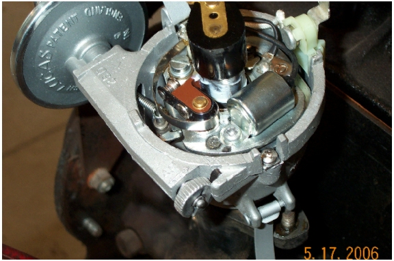 The
points in our 4 cylinder Triumph engines are mounted inside the distributor (under the
distributor cap), and they have a small rubbing block that touches a square lobe
on the distributor’s shaft. As the distributor shaft turns, the square lobe
also turns. When each of the four corners on the lobe move past the rubbing
block, the electrical contact points are forced apart (open) and the flow of
electricity stops. When a corner of the lobe is not pushing the points open,
they touch and the electricity flows through to the engine/chassis/body (ground)
and back to the negative battery terminal. By determining the exact moment that
the points open and stop the current flow, we are able to know precisely when
the coil will produce the powerful spark, and the spark plug will fire. This
knowledge will allow us to precisely set the timing.
The
points in our 4 cylinder Triumph engines are mounted inside the distributor (under the
distributor cap), and they have a small rubbing block that touches a square lobe
on the distributor’s shaft. As the distributor shaft turns, the square lobe
also turns. When each of the four corners on the lobe move past the rubbing
block, the electrical contact points are forced apart (open) and the flow of
electricity stops. When a corner of the lobe is not pushing the points open,
they touch and the electricity flows through to the engine/chassis/body (ground)
and back to the negative battery terminal. By determining the exact moment that
the points open and stop the current flow, we are able to know precisely when
the coil will produce the powerful spark, and the spark plug will fire. This
knowledge will allow us to precisely set the timing.
But before we can actually set the timing, we must be certain that the points are adjusted correctly. The points primarily stop the flow of electricity through the coil’s primary windings, but they are also important for allowing the current flow through the coil as well. Current must be able to flow through the primary coil windings long enough to set up the magnetic field, or the high voltage the plugs need won’t be created. To assure that the points are both open and closed for adequate amounts of time, the points must be adjusted properly. This is an important first step in setting your engine’s timing.
To adjust your points, you will need a screwdriver (or two), and a .015” thick feeler gauge. Remove the distributor cap and rotor to gain access to the points, then rotate the engine until the rubbing block is resting on the highest point of any corner on the square lobe. To assure proper operation, we want to adjust the gap between the two contact points to be exactly .015” when they are separated the greatest amount, so it’s important to have the rubbing block placed on a high point of the lobe.
Begin by inspecting the mating surfaces of the two contact points. They should be flat and smooth for best results, and if they appear burned or pitted, replace with a new points set. Points adjustment starts by making certain that the ignition switch is “OFF”, then gently slide the feeler gauge between the two contact points to measure the gap between them. Watch to see that the feeler gauge does not force the points apart, which would indicate too narrow of a gap (less than .015”). Too wide of a gap is easy to see, and the feeler gauge will be loose and able to be move from side to side. If either of these conditions indicates that the gap is something other than .015”, they will need to be adjusted.
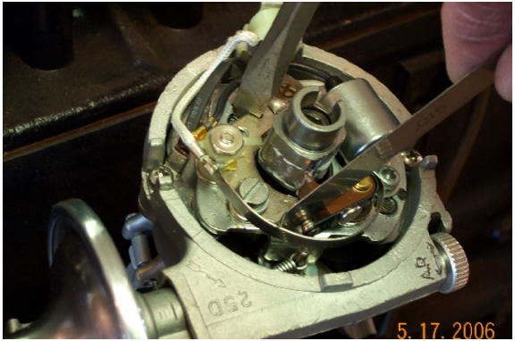 To
adjust the point gap, you’ll have to loosen the mounting screw slightly, then
move the points closer to or farther away from the cam lobe to lessen or
increase the gap. There’s a slot at one end of the points where a screwdriver
can be placed and twisted with one hand to move the points in and out, while you
drag the feeler gauge through the gap with your other hand and feel for a slight
drag. (This is easier if you leave the mounting screw just tight enough that
the points will stay where you put them!) Tighten the mounting screw and
re-check the gap with your feeler gauge. I often think that Lucas designed
these distributors to be best serviced by three handed mechanics, because it’s
not unusual for the points adjustment to change when you tighten the screw. If
the points did move and your feeler gauge doesn’t have the same slight drag as
you slide it through the gap, loosen the screw and start all over again.
Re-install the rotor when the points adjustment has been completed.
To
adjust the point gap, you’ll have to loosen the mounting screw slightly, then
move the points closer to or farther away from the cam lobe to lessen or
increase the gap. There’s a slot at one end of the points where a screwdriver
can be placed and twisted with one hand to move the points in and out, while you
drag the feeler gauge through the gap with your other hand and feel for a slight
drag. (This is easier if you leave the mounting screw just tight enough that
the points will stay where you put them!) Tighten the mounting screw and
re-check the gap with your feeler gauge. I often think that Lucas designed
these distributors to be best serviced by three handed mechanics, because it’s
not unusual for the points adjustment to change when you tighten the screw. If
the points did move and your feeler gauge doesn’t have the same slight drag as
you slide it through the gap, loosen the screw and start all over again.
Re-install the rotor when the points adjustment has been completed.
Once the points are correctly adjusted, you’re ready to set the initial timing. There are two ways to manually change the initial timing on your distributor. One is by turning the external thumbscrew, and the other is by loosening the distributor clamp and rotating the distributor body itself. We’ll use a combination of both to get the correct setting.
Because we’ll be using the external thumbscrew later in the process, it’s helpful to make sure it is resting in the middle of the adjustment range. Begin by turning the thumbscrew as far as it will go in either direction, then count the number of turns as you move it to the opposite stop. Divide that number in half, and return the screw to the middle of its range. Now you’ll have adequate adjustment in either direction should you need it later.
 We’ve
finally reached the point where we can set the initial timing, and the next
thing we must do is determine when the #1 piston is at Top Dead Center (TDC).
With the gearbox in neutral, you should be able to turn the engine (clockwise
when viewed from the front of the car) by hand until the timing mark on the
crankshaft pulley lines up with the pointer on the engine’s timing cover. As
long as someone has not assembled the hub and pulley incorrectly (see the
factory workshop manual for more on this), the #1 and #4 pistons should both be
at TDC. You can set the distributor cap loosely in place and if the rotor
points to the #1 or #4 terminal locations, you can proceed with the timing
adjustment. If you go past the place where the two marks line up, don’t just
back it up a small amount to align them. Back it up well past the correct
location, and approach the spot again with a clockwise rotation of the
crankshaft (to take up any possible “slop” due to a worn timing chain or gears
inside the engine) or rotate the crankshaft another full revolution in the
clockwise direction and try it again.
We’ve
finally reached the point where we can set the initial timing, and the next
thing we must do is determine when the #1 piston is at Top Dead Center (TDC).
With the gearbox in neutral, you should be able to turn the engine (clockwise
when viewed from the front of the car) by hand until the timing mark on the
crankshaft pulley lines up with the pointer on the engine’s timing cover. As
long as someone has not assembled the hub and pulley incorrectly (see the
factory workshop manual for more on this), the #1 and #4 pistons should both be
at TDC. You can set the distributor cap loosely in place and if the rotor
points to the #1 or #4 terminal locations, you can proceed with the timing
adjustment. If you go past the place where the two marks line up, don’t just
back it up a small amount to align them. Back it up well past the correct
location, and approach the spot again with a clockwise rotation of the
crankshaft (to take up any possible “slop” due to a worn timing chain or gears
inside the engine) or rotate the crankshaft another full revolution in the
clockwise direction and try it again.
 Now
all that’s needed is to position the distributor so that the points have opened
just enough to stop the flow of electricity through the coil with the piston at
TDC. To determine where this place is, you’ll need a 12-volt test light (which
can be purchased inexpensively from any automotive parts or tool store or home
made). Because electricity is somewhat ‘lazy’, it will always take the easiest
path as it tries to return to the battery. The current will flow through the
points when they are closed as opposed to flowing through a test light where it
would have to do some ‘work’ on the way back to the battery. When the points
open however, the only option left for the electricity to get back to the
battery is through the light and it immediately takes this new return path,
lighting the test bulb along the way! Therefore, with the ignition switch “ON”,
if you touch one side of your test light to the distributor side of the coil,
and attach the other side to a ground, the light will come on at the very
instant that the points “open” and the spark plug would fire. Simply loosen the
clamp at the base of the distributor, and rotate the distributor until you find
the spot where the light just blinks on with any movement of the distributor.
Remember that the square lobe rotates counter-clockwise, so you’re looking for
the spot where the points will just open, not the closing point on the “back
side” of the lobe’s rotation. Turn off the
ignition switch, and tighten the distributor clamp. Add a tiny amount of
lubrication to the rubbing block to reduce wear, and you’re almost done.
Now
all that’s needed is to position the distributor so that the points have opened
just enough to stop the flow of electricity through the coil with the piston at
TDC. To determine where this place is, you’ll need a 12-volt test light (which
can be purchased inexpensively from any automotive parts or tool store or home
made). Because electricity is somewhat ‘lazy’, it will always take the easiest
path as it tries to return to the battery. The current will flow through the
points when they are closed as opposed to flowing through a test light where it
would have to do some ‘work’ on the way back to the battery. When the points
open however, the only option left for the electricity to get back to the
battery is through the light and it immediately takes this new return path,
lighting the test bulb along the way! Therefore, with the ignition switch “ON”,
if you touch one side of your test light to the distributor side of the coil,
and attach the other side to a ground, the light will come on at the very
instant that the points “open” and the spark plug would fire. Simply loosen the
clamp at the base of the distributor, and rotate the distributor until you find
the spot where the light just blinks on with any movement of the distributor.
Remember that the square lobe rotates counter-clockwise, so you’re looking for
the spot where the points will just open, not the closing point on the “back
side” of the lobe’s rotation. Turn off the
ignition switch, and tighten the distributor clamp. Add a tiny amount of
lubrication to the rubbing block to reduce wear, and you’re almost done.
You’ve just set the ignition timing to fire the spark plugs when each piston has reached TDC, but Triumph has specified that this setting should actually be 4 degrees before TDC. How are we going to do this? This is the easy part. Just turn the external thumbscrew in the “A” direction (advance) as indicated by the arrow. There is a reference line through the middle the thumbscrew, and one complete turn is equal to 8 degrees of adjustment. Therefore, note the position of the reference line and turn the screw ½ turn in the “A” direction to set your ignition timing at the factory recommended 4 degrees BTDC.
Congratulations! Your timing is now set. Re-install the distributor cap, pick up all of your tools, and take that Triumph TR out for a drive!
BACK to Timing Page 1