© 2026 - Macy’s Garage, Ltd.
Macy’s Garage

America’s BEST Triumph Shop
IGNITION TIMING
Ignition Timing
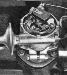
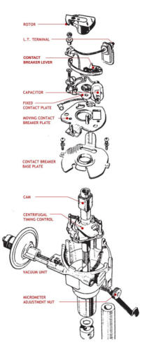
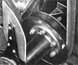
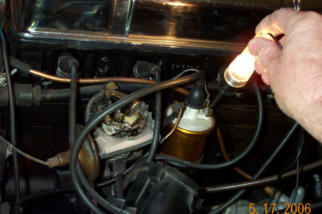
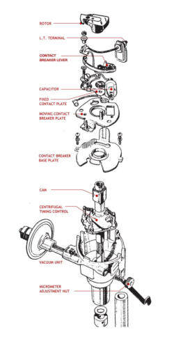
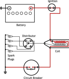
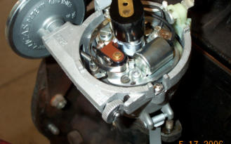
This is an extensive look into the simple task of setting ignition timing on your Triumph TR2, TR3, or TR4/4A. You may ask, “If it’s so simple, why does it require a lengthy explanation?” The answer to that question is that we’ll begin by explaining what timing is, why it’s important, and how the Triumph method is different from the way timing is “set” for most other makes. Then we will get to the actual timing procedure. Without getting into the whole 4 stroke cycle of the internal combustion engines which power our Triumph sports cars, let’s just jump right in and say that timing determines the exact instant that the spark plug will “fire” and light the compressed fuel and air mixture in each cylinder. This point is usually referred to as a certain number of degrees “before top dead center” (BTDC), a term which may require more explanation for some. Top Dead Center (TDC) is the point where the piston has completed its rise to the top of the cylinder, and the fuel/air mixture has been compressed as much as it can possibly be squeezed. Any further rotation of the crankshaft will begin to pull the piston down and away from the spark plug and cylinder head. What we’d really like to see happen is that the spark plug will fire at this exact moment, causing the fuel and air mixture to burn and expand, driving the piston down to create the power we need and the noise we love to hear. Note that I said that the fuel and air would burn and expand, not explode, as many people believe. It happens very quickly, and if you could see inside the cylinder it might resemble a small explosion, but it is a controlled burn which takes a fraction of a second to complete, thus the need to start the fuel burn a few degrees before the piston reaches the TDC position (AKA “Advanced”). The degrees that we’re referring to are degrees of rotation of the crankshaft, with 360 degrees being the total number of segments (degrees) that define a circle (and you thought you’d NEVER have a use for that high school Geometry!). Ideally the full burn should be completed when the piston has moved slightly downwards, or at about 20 degrees after top dead center (ATDC). The rate of burning for the fuel/air mixture takes a set amount of time, and the time required to complete this burn is fixed and does not change. For this reason, the timing is set so that the spark plug will fire a specific number of degrees before the piston reaches top dead center (BTDC) on the compression stroke, which allows the mixture to be completely burned at the correct point ATDC. As the engine speed increases, the timing must be “advanced” so that the spark plug will fire a greater number of degrees BTDC, allowing the fuel/air mixture the time necessary to be fully burned at the correct point for maximum power. When working correctly, the distributor will do this automatically as engine speed changes throughout normal driving. All we must do is set the starting point, the “initial timing”, and the distributor should do the rest. Our Triumph TR2-4A distributors are equipped with two separate systems for adjusting the ignition timing to meet the changing requirements of various engine speeds and throttle positions. First there are centrifugal weights inside the distributor which sense increased engine speed, and mechanically advance the timing to larger and larger numbers of degrees BTDC, giving the fuel/air mixture the time it needs to completely burn by the correct point ATDC. This mechanical advance starts working between 450 and 700 RPM and will be fully advanced, adding an extra 22 degrees BTDC, by 2400 RPM. (These figures are for a Lucas 25D4 distributor in a TR4. Other models are similar.) As engine speed slows down, the centrifugal weights don’t spin as fast, and the timing “retards” back to a lesser number of degrees BTDC. There’s also a vacuum advance chamber on the side of the distributor which can add another 6-10 degrees of advance timing BTDC, depending on throttle position and engine load. Now after hearing all of this, aren’t you glad that we only have to set the “initial” timing? The automatic advance mechanisms of our Triumph distributors were a great improvement over the earliest autos, which usually had a “spark” lever on the steering column that required the driver to continually adjust the timing as engine speeds changed. As good as we’ve got it, there have been many improvements since our Triumphs first rolled off the assembly line. All of this timing advance and retard stuff is now computer controlled on modern cars, and non-wearing parts inside of today’s control boxes means that setting timing is now a ritual reserved for those of us afflicted with “old car disease”. In days past, when setting the timing of a car was a routine procedure, a strobe light affair called a timing light was normally attached to the number 1 spark plug and the timing was adjusted while the engine was running at idle. On most cars, this procedure produced the desired results because the idle speed was lower than the engine speed where the centrifugal weights would start to advance the timing. The Triumph owner however, will not achieve the desired results when setting the timing with a timing light. If you recall from above, the mechanical advance can begin between 450 and 700 RPM. That’s pretty slow for a TR engine to idle, and without knowing exactly where it starts advancing, and by how much, we should probably use some other method to accurately set the initial timing. Fortunately, the engineers at Standard- Triumph specified a method for setting our initial timing with the engine OFF. This is nice in that it can be done in a cool engine compartment, and it keeps fingers and tools away from spinning fan belts and fan blades. Now we can roll up our sleeves and get to the “how’s”. The first “how” we need to know about to set initial timing is how we know the exact moment that a spark plug is going to fire? For that answer, I need to explain how the ignition system in our Triumphs works. It all starts with the 12-volt battery, and electricity’s desire to flow from the positive battery terminal to the negative battery terminal. Even though batteries were originally installed in our Triumphs with the positive terminal connected to ground, I’m going to explain this as if your car has been converted to negative ground, because it seems to make more sense (at least to me). In basic terms, electrical current flows from the positive battery terminal to the negative terminal. The engine’s ignition system is one of many paths that the electricity can take. The current flows from the positive battery terminal through a wire to the ignition switch, and if the switch is “ON” continues to the “+” terminal of the coil. Of course if the switch is “OFF”, then the current flow stops and the ignition system is disabled. Now the coil is an interesting part, because it has the ability to turn the 12-volt electricity from the battery into the 20-30,000 volts (or more) needed to cause a spark to jump across the spark plug terminals. How does it do that? There are actually two coils (windings) of wire inside a “coil”, a primary coil around the outside and a separate inner or secondary coil. When electricity from the battery flows through the primary windings it produces a magnetic field, which affects the inner (secondary) windings. If the current flow (from the battery) through the primary coil windings is suddenly stopped, the magnetic field collapses, which induces a current in the secondary coil windings. The much larger number of coil windings in the secondary coil cause it to produce the high voltage necessary to jump the spark plug gap, and ignite the fuel/air mixture in your engine. How is it that we are able to stop this flow of electricity through the primary coil windings each time that we want a spark plug to fire? That’s the job of the breaker points (usually referred to as simply “points”, and labeled with the British term “Circuit Breaker” in the schematic above). In our example of a negative ground battery system, a small wire from the “-“ side of the coil goes to the distributor and continues inside where it connects to the points. (If your car is positive ground, then the connections to the “+” and “-“ terminals of the coil should be reversed.) The points in our 4 cylinder Triumph engines are mounted inside the distributor (under the distributor cap), and they have a small rubbing block that touches a square lobe (4 cylinder) on the distributor’s shaft. (If you have a TR6, the lobe will be HEX shaped with 6 corners.) As the distributor shaft turns, the lobe also turns. When each of the corners on the lobe move past the points rubbing block, the electrical contact points are forced apart (open) and the flow of electricity stops. When a corner of the lobe is not pushing the points open, they touch and the electricity flows through to the engine/chassis/body (ground) and back to the negative battery terminal. By determining the exact moment that the points open and stop the current flow, we are able to know precisely when the coil will produce the powerful spark, and the spark plug will fire. This knowledge will allow us to precisely set the timing. But before we can actually set the timing, we must be certain that the points are adjusted correctly. The points primarily stop the flow of electricity through the coil’s primary windings, but they are also important for allowing the current flow through the coil as well. Current must be able to flow through the primary coil windings long enough to set up the magnetic field, or the high voltage the plugs need won’t be created. To assure that the points are both open and closed for adequate amounts of time, the points must be adjusted properly. This is an important first step in setting your engine’s timing. To adjust your points, you will need a screwdriver (or two), and a .015” thick feeler gauge. Remove the distributor cap and rotor to gain access to the points, then rotate the engine until the rubbing block is resting on the highest point of any corner on the lobe. You can rotate the engine by a) have an assistant use the hand crank at the front of the car, b) grab onto one of the original metal fan blades (NOT one of our Hurricane or other plastic fans!) and pull the engine over, c) put the car in gear and rock it forward or backward, or d) bump the starter until the points land on a high spot of the cam (be sure the gearbox is in NEUTRAL!). To assure proper operation, we want to adjust the gap between the two contact points to be exactly .015” when they are separated the greatest amount, so it’s important to have the rubbing block placed on a high point of the lobe. Begin by inspecting the mating surfaces of the two contact points. They should be flat and smooth for best results, and if they appear burned or pitted, replace with a new points set. Points adjustment starts by making certain that the ignition switch is “OFF”, then gently slide the feeler gauge between the two contact points to measure the gap between them. Watch to see that the feeler gauge does not force the points apart, which would indicate too narrow of a gap (less than .015”). Too wide of a gap is easy to see, and the feeler gauge will be loose and able to be move from side to side. If either of these conditions indicates that the gap is something other than .015”, they will need to be adjusted. To adjust the point gap, you’ll have to loosen the mounting screw slightly, then you can move the points closer to or farther away from the cam lobe to lessen or increase the gap. There’s a slot at one end of the points where a screwdriver can be placed and twisted with one hand to move the points in and out, while you drag the feeler gauge through the gap with your other hand and feel for a slight drag. (This is easier if you leave the mounting screw just tight enough that the points will stay where you put them!) Tighten the mounting screw and re-check the gap with your feeler gauge. I often think that Lucas designed these distributors to be best serviced by three handed mechanics, because it’s not unusual for the points adjustment to change when you tighten the screw. If the points did move and your feeler gauge doesn’t have the same slight drag as you slide it through the gap, loosen the screw and start all over again. Re-install the rotor when the points adjustment has been completed. Once the points are correctly adjusted, you’re ready to set the initial timing. There are two ways to manually change the initial timing on your distributor. One is by turning the external thumbscrew, and the other is by loosening the distributor clamp and rotating the distributor body itself. We’ll use a combination of both to get the correct setting. Because we’ll be using the external thumbscrew later in the process, it’s helpful to make sure it is resting in the middle of the adjustment range. Begin by turning the thumbscrew as far as it will go in either direction, then count the number of turns as you move it to the opposite stop. Divide that number in half, and return the screw to the middle of its range. Now you’ll have adequate adjustment in either direction should you need it for fine tuning later. We’ve finally reached the point where we can set the initial timing, and the next thing we must do is determine when the #1 piston is at Top Dead Center (TDC). Turn the engine clockwise (when viewed from the front of the car) until the timing mark on the crankshaft pulley lines up with the pointer on the engine’s timing cover. As long as someone has not assembled the hub and pulley incorrectly (see the factory workshop manual for more on this), the #1 and #4 pistons should both be at TDC. You can set the distributor cap loosely in place and if the rotor points to the #1 or #4 terminal locations, you can proceed with the timing adjustment. If you go past the place where the two marks line up, don’t just back it up a small amount to align them. Back it up well past the correct location, and approach the spot again with a clockwise rotation of the crankshaft (to take up any possible “slop” due to a worn timing chain or gears inside the engine) or rotate the crankshaft another full revolution in the clockwise direction and try it again. Now all that’s needed is to position the distributor so that the points have opened just enough to stop the flow of electricity through the coil with the piston at TDC. To determine where this place is, you’ll need a 12-volt test light (which can be purchased inexpensively from any automotive parts or tool store or home- made). Because electricity is somewhat ‘lazy’, it will always take the easiest path as it tries to return to the battery. The current will flow through the points when they are closed as opposed to flowing through a test light where it would have to do some ‘work’ on the way back to the battery. When the points open however, the only option left for the electricity to get back to the battery is through the light and it immediately takes this new return path, lighting the test bulb along the way! Therefore, with the ignition switch “ON”, if you touch one side of your test light to the distributor side of the coil, and attach the other side to a ground, the light will come on at the very instant that the points “open” and the spark plug would fire. Simply loosen the clamp at the base of the distributor, and rotate the distributor until you find the spot where the light just blinks on with any movement of the distributor. Remember that the square lobe rotates counter-clockwise, so you’re looking for the spot where the points will just open, not the closing point on the “back side” of the lobe’s rotation. Turn off the ignition switch, and tighten the distributor clamp. Add a tiny amount of lubrication to the rubbing block to reduce wear, and you’re almost done. You’ve just set the ignition timing to fire the spark plugs when each piston has reached TDC, but Triumph has specified that this setting should actually be 4 degrees Before TDC. How are we going to do this? This is the easy part. Just turn the external thumbscrew in the “A” direction (advance) as indicated by the arrow. There is a reference line through the middle the thumbscrew, and one complete turn is equal to 8 degrees of adjustment. Therefore, note the position of the reference line and turn the screw ½ turn in the “A” direction to set your ignition timing at the factory recommended 4 degrees BTDC. Congratulations! Your timing is now set. Re-install the distributor cap, pick up all of your tools, and take that Triumph TR out for a drive!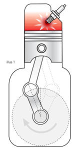


© 2026 - Macy’s Garage, Ltd.
Macy’s Garage


America’s BEST Triumph Shop

Ignition Timing
This is an extensive look into the simple task of setting ignition timing on your Triumph TR2, TR3, or TR4/4A. You may ask, “If it’s so simple, why does it require a lengthy explanation?” The answer to that question is that we’ll begin by explaining what timing is, why it’s important, and how the Triumph method is different from the way timing is “set” for most other makes. Then we will get to the actual timing procedure. Without getting into the whole 4 stroke cycle of the internal combustion engines which power our Triumph sports cars, let’s just jump right in and say that timing determines the exact instant that the spark plug will “fire” and light the compressed fuel and air mixture in each cylinder. This point is usually referred to as a certain number of degrees “before top dead center” (BTDC), a term which may require more explanation for some. Top Dead Center (TDC) is the point where the piston has completed its rise to the top of the cylinder, and the fuel/air mixture has been compressed as much as it can possibly be squeezed. Any further rotation of the crankshaft will begin to pull the piston down and away from the spark plug and cylinder head. What we’d really like to see happen is that the spark plug will fire at this exact moment, causing the fuel and air mixture to burn and expand, driving the piston down to create the power we need and the noise we love to hear. Note that I said that the fuel and air would burn and expand, not explode, as many people believe. It happens very quickly, and if you could see inside the cylinder it might resemble a small explosion, but it is a controlled burn which takes a fraction of a second to complete, thus the need to start the fuel burn a few degrees before the piston reaches the TDC position (AKA “Advanced”). The degrees that we’re referring to are degrees of rotation of the crankshaft, with 360 degrees being the total number of segments (degrees) that define a circle (and you thought you’d NEVER have a use for that high school Geometry!). Ideally the full burn should be completed when the piston has moved slightly downwards, or at about 20 degrees after top dead center (ATDC). The rate of burning for the fuel/air mixture takes a set amount of time, and the time required to complete this burn is fixed and does not change. For this reason, the timing is set so that the spark plug will fire a specific number of degrees before the piston reaches top dead center (BTDC) on the compression stroke, which allows the mixture to be completely burned at the correct point ATDC. As the engine speed increases, the timing must be “advanced” so that the spark plug will fire a greater number of degrees BTDC, allowing the fuel/air mixture the time necessary to be fully burned at the correct point for maximum power. When working correctly, the distributor will do this automatically as engine speed changes throughout normal driving. All we must do is set the starting point, the “initial timing”, and the distributor should do the rest. Our Triumph TR2-4A distributors are equipped with two separate systems for adjusting the ignition timing to meet the changing requirements of various engine speeds and throttle positions. First there are centrifugal weights inside the distributor which sense increased engine speed, and mechanically advance the timing to larger and larger numbers of degrees BTDC, giving the fuel/air mixture the time it needs to completely burn by the correct point ATDC. This mechanical advance starts working between 450 and 700 RPM and will be fully advanced, adding an extra 22 degrees BTDC, by 2400 RPM. (These figures are for a Lucas 25D4 distributor in a TR4. Other models are similar.) As engine speed slows down, the centrifugal weights don’t spin as fast, and the timing “retards” back to a lesser number of degrees BTDC. There’s also a vacuum advance chamber on the side of the distributor which can add another 6-10 degrees of advance timing BTDC, depending on throttle position and engine load. Now after hearing all of this, aren’t you glad that we only have to set the “initial” timing? The automatic advance mechanisms of our Triumph distributors were a great improvement over the earliest autos, which usually had a “spark” lever on the steering column that required the driver to continually adjust the timing as engine speeds changed. As good as we’ve got it, there have been many improvements since our Triumphs first rolled off the assembly line. All of this timing advance and retard stuff is now computer controlled on modern cars, and non-wearing parts inside of today’s control boxes means that setting timing is now a ritual reserved for those of us afflicted with “old car disease”. In days past, when setting the timing of a car was a routine procedure, a strobe light affair called a timing light was normally attached to the number 1 spark plug and the timing was adjusted while the engine was running at idle. On most cars, this procedure produced the desired results because the idle speed was lower than the engine speed where the centrifugal weights would start to advance the timing. The Triumph owner however, will not achieve the desired results when setting the timing with a timing light. If you recall from above, the mechanical advance can begin between 450 and 700 RPM. That’s pretty slow for a TR engine to idle, and without knowing exactly where it starts advancing, and by how much, we should probably use some other method to accurately set the initial timing. Fortunately, the engineers at Standard-Triumph specified a method for setting our initial timing with the engine OFF. This is nice in that it can be done in a cool engine compartment, and it keeps fingers and tools away from spinning fan belts and fan blades. Now we can roll up our sleeves and get to the “how’s”. The first “how” we need to know about to set initial timing is how we know the exact moment that a spark plug is going to fire? For that answer, I need to explain how the ignition system in our Triumphs works. It all starts with the 12-volt battery, and electricity’s desire to flow from the positive battery terminal to the negative battery terminal. Even though batteries were originally installed in our Triumphs with the positive terminal connected to ground, I’m going to explain this as if your car has been converted to negative ground, because it seems to make more sense (at least to me). In basic terms, electrical current flows from the positive battery terminal to the negative terminal. The engine’s ignition system is one of many paths that the electricity can take. The current flows from the positive battery terminal through a wire to the ignition switch, and if the switch is “ON” continues to the “+” terminal of the coil. Of course if the switch is “OFF”, then the current flow stops and the ignition system is disabled. Now the coil is an interesting part, because it has the ability to turn the 12-volt electricity from the battery into the 20- 30,000 volts (or more) needed to cause a spark to jump across the spark plug terminals. How does it do that? There are actually two coils (windings) of wire inside a “coil”, a primary coil around the outside and a separate inner or secondary coil. When electricity from the battery flows through the primary windings it produces a magnetic field, which affects the inner (secondary) windings. If the current flow (from the battery) through the primary coil windings is suddenly stopped, the magnetic field collapses, which induces a current in the secondary coil windings. The much larger number of coil windings in the secondary coil cause it to produce the high voltage necessary to jump the spark plug gap, and ignite the fuel/air mixture in your engine. How is it that we are able to stop this flow of electricity through the primary coil windings each time that we want a spark plug to fire? That’s the job of the breaker points (usually referred to as simply “points”, and labeled with the British term “Circuit Breaker” in the schematic above). In our example of a negative ground battery system, a small wire from the “-“ side of the coil goes to the distributor and continues inside where it connects to the points. (If your car is positive ground, then the connections to the “+” and “- “ terminals of the coil should be reversed.) The points in our 4 cylinder Triumph engines are mounted inside the distributor (under the distributor cap), and they have a small rubbing block that touches a square lobe (4 cylinder) on the distributor’s shaft. (If you have a TR6, the lobe will be HEX shaped with 6 corners.) As the distributor shaft turns, the lobe also turns. When each of the corners on the lobe move past the points rubbing block, the electrical contact points are forced apart (open) and the flow of electricity stops. When a corner of the lobe is not pushing the points open, they touch and the electricity flows through to the engine/chassis/body (ground) and back to the negative battery terminal. By determining the exact moment that the points open and stop the current flow, we are able to know precisely when the coil will produce the powerful spark, and the spark plug will fire. This knowledge will allow us to precisely set the timing. But before we can actually set the timing, we must be certain that the points are adjusted correctly. The points primarily stop the flow of electricity through the coil’s primary windings, but they are also important for allowing the current flow through the coil as well. Current must be able to flow through the primary coil windings long enough to set up the magnetic field, or the high voltage the plugs need won’t be created. To assure that the points are both open and closed for adequate amounts of time, the points must be adjusted properly. This is an important first step in setting your engine’s timing. To adjust your points, you will need a screwdriver (or two), and a .015” thick feeler gauge. Remove the distributor cap and rotor to gain access to the points, then rotate the engine until the rubbing block is resting on the highest point of any corner on the lobe. You can rotate the engine by a) have an assistant use the hand crank at the front of the car, b) grab onto one of the original metal fan blades (NOT one of our Hurricane or other plastic fans!) and pull the engine over, c) put the car in gear and rock it forward or backward, or d) bump the starter until the points land on a high spot of the cam (be sure the gearbox is in NEUTRAL!). To assure proper operation, we want to adjust the gap between the two contact points to be exactly .015” when they are separated the greatest amount, so it’s important to have the rubbing block placed on a high point of the lobe. Begin by inspecting the mating surfaces of the two contact points. They should be flat and smooth for best results, and if they appear burned or pitted, replace with a new points set. Points adjustment starts by making certain that the ignition switch is “OFF”, then gently slide the feeler gauge between the two contact points to measure the gap between them. Watch to see that the feeler gauge does not force the points apart, which would indicate too narrow of a gap (less than .015”). Too wide of a gap is easy to see, and the feeler gauge will be loose and able to be move from side to side. If either of these conditions indicates that the gap is something other than .015”, they will need to be adjusted. To adjust the point gap, you’ll have to loosen the mounting screw slightly, then you can move the points closer to or farther away from the cam lobe to lessen or increase the gap. There’s a slot at one end of the points where a screwdriver can be placed and twisted with one hand to move the points in and out, while you drag the feeler gauge through the gap with your other hand and feel for a slight drag. (This is easier if you leave the mounting screw just tight enough that the points will stay where you put them!) Tighten the mounting screw and re-check the gap with your feeler gauge. I often think that Lucas designed these distributors to be best serviced by three handed mechanics, because it’s not unusual for the points adjustment to change when you tighten the screw. If the points did move and your feeler gauge doesn’t have the same slight drag as you slide it through the gap, loosen the screw and start all over again. Re-install the rotor when the points adjustment has been completed. Once the points are correctly adjusted, you’re ready to set the initial timing. There are two ways to manually change the initial timing on your distributor. One is by turning the external thumbscrew, and the other is by loosening the distributor clamp and rotating the distributor body itself. We’ll use a combination of both to get the correct setting. Because we’ll be using the external thumbscrew later in the process, it’s helpful to make sure it is resting in the middle of the adjustment range. Begin by turning the thumbscrew as far as it will go in either direction, then count the number of turns as you move it to the opposite stop. Divide that number in half, and return the screw to the middle of its range. Now you’ll have adequate adjustment in either direction should you need it for fine tuning later. We’ve finally reached the point where we can set the initial timing, and the next thing we must do is determine when the #1 piston is at Top Dead Center (TDC). Turn the engine clockwise (when viewed from the front of the car) until the timing mark on the crankshaft pulley lines up with the pointer on the engine’s timing cover. As long as someone has not assembled the hub and pulley incorrectly (see the factory workshop manual for more on this), the #1 and #4 pistons should both be at TDC. You can set the distributor cap loosely in place and if the rotor points to the #1 or #4 terminal locations, you can proceed with the timing adjustment. If you go past the place where the two marks line up, don’t just back it up a small amount to align them. Back it up well past the correct location, and approach the spot again with a clockwise rotation of the crankshaft (to take up any possible “slop” due to a worn timing chain or gears inside the engine) or rotate the crankshaft another full revolution in the clockwise direction and try it again. Now all that’s needed is to position the distributor so that the points have opened just enough to stop the flow of electricity through the coil with the piston at TDC. To determine where this place is, you’ll need a 12-volt test light (which can be purchased inexpensively from any automotive parts or tool store or home-made). Because electricity is somewhat ‘lazy’, it will always take the easiest path as it tries to return to the battery. The current will flow through the points when they are closed as opposed to flowing through a test light where it would have to do some ‘work’ on the way back to the battery. When the points open however, the only option left for the electricity to get back to the battery is through the light and it immediately takes this new return path, lighting the test bulb along the way! Therefore, with the ignition switch “ON”, if you touch one side of your test light to the distributor side of the coil, and attach the other side to a ground, the light will come on at the very instant that the points “open” and the spark plug would fire. Simply loosen the clamp at the base of the distributor, and rotate the distributor until you find the spot where the light just blinks on with any movement of the distributor. Remember that the square lobe rotates counter-clockwise, so you’re looking for the spot where the points will just open, not the closing point on the “back side” of the lobe’s rotation. Turn off the ignition switch, and tighten the distributor clamp. Add a tiny amount of lubrication to the rubbing block to reduce wear, and you’re almost done. You’ve just set the ignition timing to fire the spark plugs when each piston has reached TDC, but Triumph has specified that this setting should actually be 4 degrees Before TDC. How are we going to do this? This is the easy part. Just turn the external thumbscrew in the “A” direction (advance) as indicated by the arrow. There is a reference line through the middle the thumbscrew, and one complete turn is equal to 8 degrees of adjustment. Therefore, note the position of the reference line and turn the screw ½ turn in the “A” direction to set your ignition timing at the factory recommended 4 degrees BTDC. Congratulations! Your timing is now set. Re-install the distributor cap, pick up all of your tools, and take that Triumph TR out for a drive!